| Previous | Next |
1. Solaris TCPIP Protocol Suite (Overview)
2. Planning an IPv4 Addressing Scheme (Tasks
3. Planning an IPv6 Addressing Scheme (Overview)
4. Planning an IPv6 Network (Tasks)
5. Configuring TCP/IP Network Services and IPv4 Addressing (Tasks)
6. Administering Network Interfaces (Tasks)
Interface Administration (Task Map)
Basics for Administering Physical Interfaces
Administering Individual Network Interfaces
How to Obtain Interface Status
How to Configure a Physical Interface After System Installation
How to Remove a Physical Interface
SPARC: How to Ensure That the MAC Address of an Interface Is Unique
Administering Virtual Local Area Networks
Administering Link Aggregations
How to Create a Link Aggregation
Configuring and Communicating Over WiFi Interfaces
How to Connect to a WiFi Network
7. Enabling IPv6 on a Network (Tasks)
8. Administering a TCP/IP Network (Tasks)
9. Troubleshooting Network Problems (Tasks)
10. TCP/IP and IPv4 in Depth (Reference)
12. About Solaris DHCP (Overview)
13. Planning for DHCP Service (Tasks)
14. Configuring the DHCP Service (Tasks)
15. Administering DHCP (Tasks)
16. Configuring and Administering DHCP Clients
17. Troubleshooting DHCP (Reference)
18. DHCP Commands and Files (Reference)
19. IP Security Architecture (Overview)
21. IP Security Architecture (Reference)
22. Internet Key Exchange (Overview)
24. Internet Key Exchange (Reference)
25. Solaris IP Filter (Overview)
28. Administering Mobile IP (Tasks)
29. Mobile IP Files and Commands (Reference)
30. Introducing IPMP (Overview)
31. Administering IPMP (Tasks)
Part VI IP Quality of Service (IPQoS)
32. Introducing IPQoS (Overview)
33. Planning for an IPQoS-Enabled Network (Tasks)
34. Creating the IPQoS Configuration File (Tasks)
35. Starting and Maintaining IPQoS (Tasks)
36. Using Flow Accounting and Statistics Gathering (Tasks)
Administering Link Aggregations
The Solaris OS supports the organization of network interfaces into link aggregations. A link aggregation consists of several interfaces on a system that are configured together as a single, logical unit. Link aggregation, also referred to as trunking, is defined in the IEEE 802.3ad Link Aggregation Standard.
The IEEE 802.3ad Link Aggregation Standard provides a method to combine the capacity of multiple full-duplex Ethernet links into a single logical link. This link aggregation group is then treated as though it were, in fact, a single link.
The following are features of link aggregations:
Increased bandwidth – The capacity of multiple links is combined into one logical link.
Automatic failover/failback – Traffic from a failed link is failed over to working links in the aggregation.
Load balancing – Both inbound and outbound traffic is distributed according to user selected load balancing policies, such as source and destination MAC or IP addresses.
Support for redundancy – Two systems can be configured with parallel aggregations.
Improved administration – All interfaces are administered as a single unit.
Less drain on the network address pool – The entire aggregation is assigned one IP address.
Link Aggregation Basics
The basic link aggregation topology involves a single aggregation that is composed of a set of physical interfaces. You might use the basic link aggregation in the following situations:
For systems that run an application with distributed heavy traffic, you can dedicate an aggregation to that application's traffic.
For sites with limited IP address space that nevertheless require large amounts of bandwidth, you need only one IP address for a large aggregation of interfaces.
For sites that need to hide the existence of internal interfaces, the IP address of the aggregation hides its interfaces from external applications.
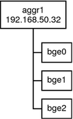
Figure 6-3 shows an aggregation for a server that hosts a popular web site. The site requires increased bandwidth for query traffic between Internet customers and the site's database server. For security purposes, the existence of the individual interfaces on the server must be hidden from external applications. The solution is the aggregation aggr1 with the IP address 192.168.50.32. This aggregation consists of three interfaces,bge0–2. These interfaces are dedicated to sending out traffic in response to customer queries. The outgoing address on packet traffic from all the interfaces is the IP address of aggr1, 192.168.50.32.
Figure 6-3 Basic Link Aggregation Topology

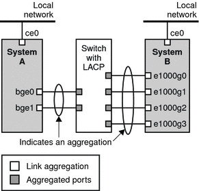
Figure 6-4 depicts a local network with two systems, each of which has an aggregation configured. The two systems are connected by a switch. If you need to run an aggregation through a switch, that switch must support aggregation technology. This type of configuration is particularly useful for high availability and redundant systems.
In the figure, System A has an aggregation that consists of two interfaces, bge0 and bge1. These interfaces are connected to the switch through aggregated ports. System B has an aggregation of four interfaces, e1000g0 throughe100g3. These interfaces are also connected to aggregated ports on the switch.
Figure 6-4 Aggregation Topology With Switch

Back-to-Back Link Aggregations
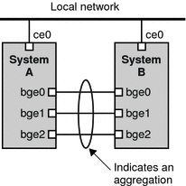
The back-to-back link aggregation topology involves two separate systems that are cabled directly to each other, as shown in the following figure. The systems run parallel aggregations.
Figure 6-5 Basic Back-to-Back Aggregation Topology

In this example, device bge0 on System A is directly linked to bge0 on System B, and so on. In this way, Systems A and B can support redundancy and high availability, as well as high-speed communications between both servers. Each server also has interface ce0 configured for traffic flow with the local network.
The most common application for back-to-back aggregations is mirrored database servers. Both servers need to be updated together and therefore require significant bandwidth, high-speed traffic flow, and reliability. Data centers are the most common users of back-to-back link aggregations.
Policies and Load Balancing
If you plan to use a link aggregation, consider defining a policy for outgoing traffic. This policy specifies how you want packets to be distributed across the available links of an aggregation, thus establishing load balancing. The following are the possible layer specifiers and their significance for the aggregation policy:
L2 - Determines the outgoing link by hashing the MAC (L2) header of each packet
L3 - Determines the outgoing link by hashing the IP (L3) header of each packet
L4 - Determines the outgoing link by hashing the TCP, UDP, or other ULP (L4) header of each packet
Any combination of these policies is also valid. The default policy is L4. For more information, refer to the dladm(1M) man page.
Aggregation Mode and Switches
If your aggregation topology involves connection through a switch, you must note whether the switch supports link aggregation control protocol (LACP). If the switch supports LACP, you must configure LACP for the switch and the aggregation. However, you can define one of the following modes in which LACP is to operate:
Off mode – The default mode for aggregations. LACP packets, which are called LACPDUs are not generated.
Active mode – The system generates LACPDUs at regular intervals, which you can specify.
Passive mode – The system generates an LACPDU only when it receives an LACPDU from the switch. When both the aggregation and the switch are configured in passive mode, they cannot exchange LACPDUs.
See the dladm(1M) man page and the switch manufacturer's documentation for syntax information.
Requirements for Aggregations
Your aggregation configuration is bound by the following requirements:
You must use the dladm command to configure aggregations.
An interface that has been plumbed cannot become a member of an aggregation.
All interfaces in the aggregation must run at the same speed and in full duplex mode.
You must set the value for MAC addresses to “true” in the EEPROM parameter local-mac-address? For instructions, refer to SPARC: How to Ensure That the MAC Address of an Interface Is Unique.
“Legacy” data link provider interfaces (DLPI ), such as the ce interface do not support Solaris link aggregations. Instead, you must configure aggregations for legacy devices by using Sun Trunking. You cannot configure aggregations for legacy devices by using the dladm command. For more information about Sun Trunking, refer to the Sun Trunking 1.3 Installation and User's Guide.
How to Create a Link Aggregation
Before You Begin
Note - Link aggregation only works on full-duplex, point-to-point links that operate at identical speeds. Make sure that the interfaces in your aggregation conform to this requirement.
If you are using a switch in your aggregation topology, make sure that you have done the following on the switch:
Configured the ports to be used as an aggregation
If the switch supports LACP, configured LACP in either active mode or passive mode
- Assume the Primary Administrator role, or become superuser.
The Primary Administrator role includes the Primary Administrator profile. To create the role and assign the role to a user, see Chapter 2, Working With the Solaris Management Console (Tasks), in System Administration Guide: Basic Administration.
- Determine which interfaces are currently installed on your system.
# dladm show-link
- Determine which interfaces have been plumbed.
# ifconfig -a
- Create an aggregation.
# dladm create-aggr -d interface key
- interface
Represents the device name of the interface to become part of the aggregation.
- key
Is the number that identifies the aggregation. The lowest key number is 1. Zeroes are not allowed as keys.
For example:
# dladm create-aggr -d bge0 -d bge1 1
- Configure and plumb the newly created aggregation.
# ifconfig aggrkey plumb IP-address up
For example:
# ifconfig aggr1 plumb 192.168.84.14 up
- Check the status of the aggregation you just created.
# dladm show-aggr
You receive the following output:
key: 1 (0x0001) policy: L4      address: 0:3:ba:7:84:5e (auto)
           device   address           speed         duplex  link    state
           bge0     0:3:ba:7:84:5e    1000  Mbps    full    up      attached
           bge1     0:3:ba:7:84:5e    0     Mbps    unknown down    standby
The output shows that an aggregation with the key of 1 and a policy of L4 was created. Note that the interfaces are known by the MAC address 0:3:ba:7:84:5e, which is the system MAC address.
- (Optional) Make the IP configuration of the link aggregation persist across reboots.
- For link aggregations with IPv4 addresses, create an /etc/hostname.aggr.key file. For IPv6–based link aggregations, create an /etc/hostname6.aggr.key file.
- Enter the IPv4 or IPv6 address of the link aggregation into the file.
For example, you would create the following file for the aggregation that is created in this procedure:
# vi /etc/hostname.aggr1
192.168.84.14
- Perform a reconfiguration boot.
# reboot -- -r
- Verify that the link aggregation configuration you entered in the /etc/hostname.aggrkey file has been
configured.
# ifconfig -a
.
.
aggr1: flags=1000843 <UP,BROADCAST,RUNNING,MULTICAST,IPv4> mtu 1500 index 3
        inet 192.168.84.14 netmask ff000000 broadcast 192.255.255.
This example shows the commands that are used to create a link aggregation with two devices, bge0 and bge1, and the resulting output.
# dladm show-link
ce0             type: legacy    mtu: 1500       device: ce0
ce1             type: legacy    mtu: 1500       device: ce1
bge0            type: non-vlan  mtu: 1500       device: bge0
bge1            type: non-vlan  mtu: 1500       device: bge1
bge2            type: non-vlan  mtu: 1500       device: bge2
# ifconfig -a
lo0: flags=2001000849 <UP,LOOPBACK,RUNNING,MULTICAST,IPv4,VIRTUAL> mtu 8232 index 1
        inet 127.0.0.1 netmask ff000000
ce0: flags=1000843 <UP,BROADCAST,RUNNING,MULTICAST,IPv4> mtu 1500 index 2
        inet 192.168.84.253 netmask ffffff00 broadcast 192.168.84.255
        ether 0:3:ba:7:84:5e
# dladm create-aggr -d bge0 -d bge1 1
# ifconfig aggr1 plumb 192.168.84.14 up
# dladm show-aggr
key: 1 (0x0001) policy: L4      address: 0:3:ba:7:84:5e (auto)
     device   address           speed         duplex  link    state
     bge0     0:3:ba:7:84:5e    1000  Mbps    full    up      attached
     bge1     0:3:ba:7:84:5e    0     Mbps    unknown down    standby

# ifconfig -a
lo0: flags=2001000849 <UP,LOOPBACK,RUNNING,MULTICAST,IPv4,VIRTUAL> mtu 8232 index 1
        inet 127.0.0.1 netmask ff000000
ce0: flags=1000843 <UP,BROADCAST,RUNNING,MULTICAST,IPv4> mtu 1500 index 2
        inet 192.168.84.253 netmask ffffff00 broadcast 192.168.84.255
        ether 0:3:ba:7:84:5e
aggr1: flags=1000843 <UP,BROADCAST,RUNNING,MULTICAST,IPv4> mtu 1500 index 3
        inet 192.168.84.14 netmask ff000000 broadcast 192.255.255.255
        ether 0:3:ba:7:84:5e
Note that the two interfaces that were used for the aggregation were not previously plumbed by ifconfig.
How to Modify an Aggregation
This procedure shows how to make the following changes to an aggregation definition:
Modifying the policy for the aggregation
Changing the mode for the aggregation
Removing an interface from the aggregation
- Assume the Primary Administrator role, or become superuser.
The Primary Administrator role includes the Primary Administrator profile. To create the role and assign the role to a user, see Chapter 2, Working With the Solaris Management Console (Tasks), in System Administration Guide: Basic Administration.
- Modify the aggregation to change the policy.
# dladm modify-aggr -Ppolicy key
- policy
Represents one or more of the policies L2, L3, and L4, as explained in Policies and Load Balancing.
- key
Is a number that identifies the aggregation. The lowest key number is 1. Zeroes are not allowed as keys.
- If LACP is running on the switch to which the devices in
the aggregation are attached, modify the aggregation to support LACP.
If the switch runs LACP in passive mode, be sure to configure active mode for your aggregation.
# dladm modify-aggr -l LACP mode -t timer-value key
- -l LACP mode
Indicates the LACP mode in which the aggregation is to run. The values are active, passive, and off.
- -t timer-value
Indicates the LACP timer value, either short or long.
- key
Is a number that identifies the aggregation. The lowest key number is 1. Zeroes are not allowed as keys.
This example shows how to modify the policy of aggregation aggr1 to L2 and then turn on active LACP mode.
# dladm modify-aggr -P L2 1
# dladm modify-aggr -l active -t short 1
# dladm show-aggr
key: 1 (0x0001) policy: L2      address: 0:3:ba:7:84:5e (auto)
     device   address           speed         duplex  link    state
     bge0     0:3:ba:7:84:5e    1000  Mbps    full    up      attached
     bge1     0:3:ba:7:84:5e    0     Mbps    unknown down    standby
How to Remove an Interface From an Aggregation
- Assume the Primary Administrator role, or become superuser.
The Primary Administrator role includes the Primary Administrator profile. To create the role and assign the role to a user, see Chapter 2, Working With the Solaris Management Console (Tasks), in System Administration Guide: Basic Administration.
- Remove an interface from the aggregation.
# dladm remove-aggr -d interface
This example shows how to remove the interfaces of the aggregation aggr1.
# dladm show-aggr
key: 1 (0x0001) policy: L2      address: 0:3:ba:7:84:5e (auto)
     device   address           speed         duplex  link    state
     bge0     0:3:ba:7:84:5e    1000  Mbps    full    up      attached
     bge1     0:3:ba:7:84:5e    0     Mbps    unknown down    standby
# dladm remove-aggr -d bge1 1
# dladm show-aggr
key: 1 (0x0001) policy: L2      address: 0:3:ba:7:84:5e (auto)
     device    address           speed         duplex  link    state
     bge0      0:3:ba:7:84:5e    1000  Mbps    full    up      attached
How to Delete an Aggregation
- Assume the Primary Administrator role, or become superuser.
The Primary Administrator role includes the Primary Administrator profile. To create the role and assign the role to a user, see Chapter 2, Working With the Solaris Management Console (Tasks), in System Administration Guide: Basic Administration.
- Delete the aggregation.
# dladm remove-aggr key
- key
Is a number that identifies the aggregation. The lowest key number is 1. Zeroes are not allowed as keys.
This example shows how to remove the aggregation aggr1.
# dladm show-aggr
key: 1 (0x0001) policy: L2      address: 0:3:ba:7:84:5e (auto)
     device   address           speed     duplex  link    state
          # dladm remove-aggr -d bge0 1
| Previous | Next |